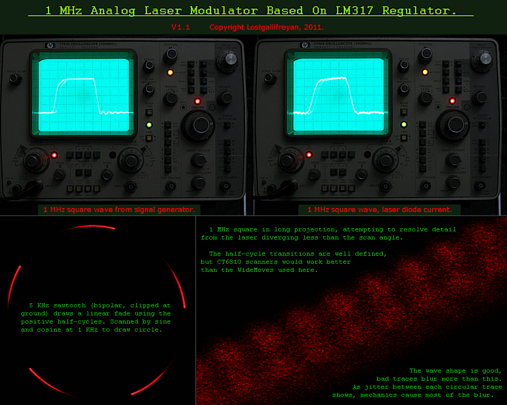
1 MHz Analog Laser Driver.Linear modulator based on LM317 Regulator.Original article published in Sam's LaserFAQ, here.Description: |

|
How to use it: Details of use: |

|
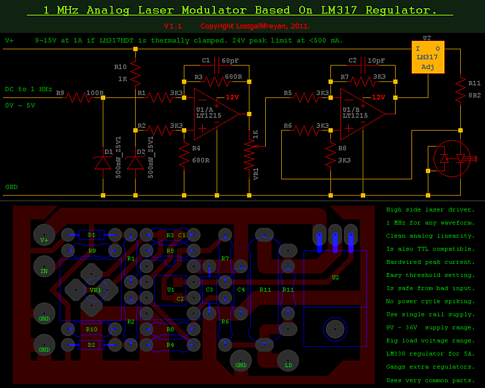
Wire the pot so the ground is on the top end of the scale, a fully clockwise turn should ground the wiper. Use a GOOD pot, a sealed cermet or polymer track type. Even better, a potentiometer IC which offers several useful advantages for remote control as well as low noise and long life and secure retention of setting... At minimum it's all modulation, at maximum it's all fixed output current. The board has space for a single turn cermet preset pot, and four pads, so it can be mounted such that full clockwise turn can be all modulation, or full fixed output current, depending on preference. Any input subtracts from the reference voltage, and full input almost cancels it (but not quite, it it wise to avoid ground clipping in the op-amp if possible, to prevent strange behaviour at high speeds). When this inverted modulation is passed to the second stage via the pot, it subtracts from the current setting resistor's low side voltage, making the regulator reduce its current when the original input falls. At full input or pot maximum, as either case removes input to the second stage inverting input, the second stage output equals the current setting resistor's low side voltage, which in turn means the maximum current is solely determined by that resistor. The input's zener diode prevents a signal capable of driving the regulator to output more current, as does clipping at ground in the first stage even if the zener failed. The pot is also useful as a simple fader in absence of modulation, and if set to minimum position, allows remote dimming by varying an input DC voltage from 0V, to 5V for full output. Note that local dimming with the inbuilt pot overrides the modulation at maximum setting, you cannot modulate to reduce from maximum preset brightness. If you need to do this, as with some inbuilt laser modulators, you need to invert your signal before input to the driver, as is usual in any laser system that conforms to high side drive and active high input. Usually you'd only need to do this when the laser's inbuilt modulator does not conform. The second op-amp stage takes into account whatever the laser diode voltage drop is, so any dynamic shift in that value with changes in current is automatically compensated. Dangerous input, including overvoltage, reversed polarity, even moderate static discharge, is prevented from harming the driver or laser diode by a combination of input resistor and zener diode. The zener's capacitance also forms a filter with the 100R resistor, that allows clean waveshapes at 1 MHz while slowing down any transients fast enough to cause trouble later if they got through. Don't tempt fate by being careless of static discharge, otherwise add a large 6V metal oxide varistor across the input socket if you insist on riding the lightning. C3 and C4 on the board are for power supply decoupling. Make C3, the closest one to the op-amp, a 0.1µF low ESR ceramic, and C4 a 40V 22µF low ESR tantalum. Another important aspect of the use of two op-amp stages is the repair of mark/space ratio symmetry at high speed due to differences in rise and fall time. As one stage falls when the other rises, the differences cancel to an extent great enough to allow higher performance than with a single stage. Despite two stages slowing the transitions more than one, this is still true, as scoping the output of the first stage, then the second, will demonstrate. A small asymmetry exists at 1 MHz anyway, but far less than appears on the first stage. NOTE: An SPDT switch could select either the input on the first stage, or the output from it, to feed to the pot. This could allow a simple way to get compatibility for systems with inverted signaling, but the price will be a loss of symmetry correction for high speeds because in this case the first op-amp stage is not used. As you can gang output resistors and diodes to one regulator, and multiple regulators to ONE driver, you can set the current setting resistor for any diode that falls outside spec for a given batch. Calculate resistance by 1.25/A where A is required maximum current. Pick a preferred value above the calculated value, then calculate the required resistance to parallel with it, to get the total resistance needed if the initial value is more than 1% out, and to compensate for any significant diode forward voltage deviation (look for unusually dim or bright outputs with common drive set halfway). Calculate to find the power dissipation for each, so they won't burn out in use. The board layout has space for this, when driving a single diode up to at least 1.5A, but bigger resistors may be needed if using an LM338. The circuit must monitor the low side of ONE current setting resistor, but other diodes and resistors can safely use whatever current the regulator makes available to them. Ganging regulators is the same, common the ADJ pins, you still only need to monitor ONE resistor. Ideally, pick all duplicate components from the same high grade batch, and leave a little headroom to allow for slight differences. The odd loss of a laser diode, if you like to push the envelope, is more than made up for by the ease of building a simple array extensible by few, and cheap, parts. This is one of the joys of a proper high side driver. No matter how big the laser system, you only need three drivers, one per primary colour (plus one for any unusual extra colours you might use, such as 405 nm). You do NOT need one per diode here! :) Given the quality of the ideal potentiometer, this is a Good Thing, those cost.... But, less than a diode driver costs so this still saves plenty. Remember that the high load voltage capability (up to about 3V short of supply, which in turn can be up to 36V) means you can string laser diodes in SERIES from one resistor too, as an alternative to parallel connection. With this driver (fitted with LM338 instead of LM317) you could likely modulate a 32V 100W floodlamp LED with a 1 MHz sawtooth wave, but I can't think why the hell anyone would want to... |